The Ably Blog
Notes from the people building realtime
Ably engineering
Latest writing tagged Ably engineering.
Recent posts
Showing 1–12 of 68
Ably engineering
Introducing tfgen: configure your Terraform stacks using plain Go

Ably engineering
One person, one vote: building live voting with message annotations

Ably engineering
Nobody trusted our internal dashboards. Now they live in code

Ably engineering
Engineering message appends for AI Transport: three vignettes

Ably engineering
AWS us-east-1 outage: How Ably’s multi-region architecture held up
Realtime experiences
Patterns for building realtime features

Ably engineering
Scaling Pub/Sub with WebSockets and Redis

Ably engineering
Data integrity in Ably Pub/Sub

Ably engineering
Optimizing global message transit latency: a journey through TCP configuration
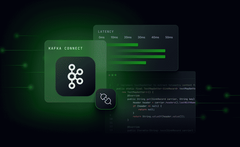
Ably engineering
Measuring and minimizing latency in a Kafka Sink Connector
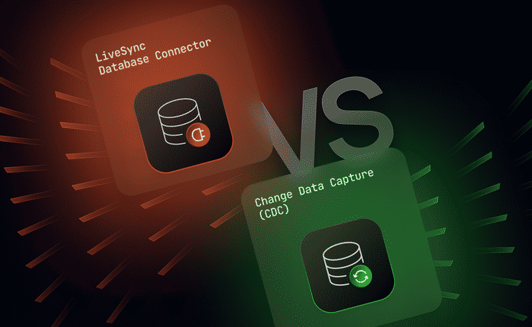
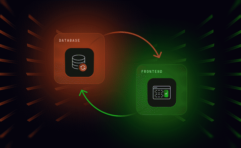
Ably engineering
Database generated events: LiveSync’s database connector vs CDC
Ably engineering